 Between 1914 and 1935, (with the exception of one, in 1951) dams were built in the Brown Duck, Garfield and Swift Creek Basins in the Lake Fork and Yellowstone Watersheds (see map, left) in what is now the High Uintas Wilderness Area. Between 1914 and 1935, (with the exception of one, in 1951) dams were built in the Brown Duck, Garfield and Swift Creek Basins in the Lake Fork and Yellowstone Watersheds (see map, left) in what is now the High Uintas Wilderness Area.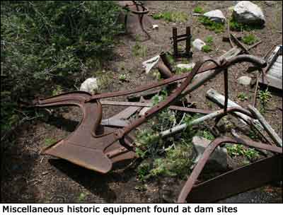
In the Lake Fork Watershed, construction began in 1917 in the remote Brown Duck Basin. By November 1919, small earthen dams were in place at the outlets of three inter-connected natural lakes: Brown Duck, Kidney, and Island Lakes. The dams were completed at the tail end of a two-year drought that threatened losses on over 50,000 acres of agricultural fields (Fraser et al. 1989:62). Although the dams in Brown Duck Basin helped meet irrigation requirements of the region, their capacity was viewed as insufficient for the growing number of acres cultivated in the valleys below. The call for more water was met by further irrigation water storage projects along adjacent drainage systems such as the Yellowstone Watershed (Garfield and Swift Creek Basins), which began in the 1920s.
 Constructing the dams was hard work. Transporting necessary construction materials to the work site was a difficult task in and of itself. Rough roads were cut to the construction work sites as early as 1916. Teams of horses and men hauled up dynamite, concrete mix, corrugated metal pipe, canal gates, excavation equipment, tools, rebar, food, and other supplies. Steep terrain complicated the transport of heavy, bulky, and explosive materials. As a result, the bulk of heavy building materials were transported to the dam sites during winter months when sturdy sleds or sleighs could be used (Fraser et al. 1989:67, 71). Constructing the dams was hard work. Transporting necessary construction materials to the work site was a difficult task in and of itself. Rough roads were cut to the construction work sites as early as 1916. Teams of horses and men hauled up dynamite, concrete mix, corrugated metal pipe, canal gates, excavation equipment, tools, rebar, food, and other supplies. Steep terrain complicated the transport of heavy, bulky, and explosive materials. As a result, the bulk of heavy building materials were transported to the dam sites during winter months when sturdy sleds or sleighs could be used (Fraser et al. 1989:67, 71).
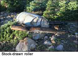
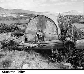
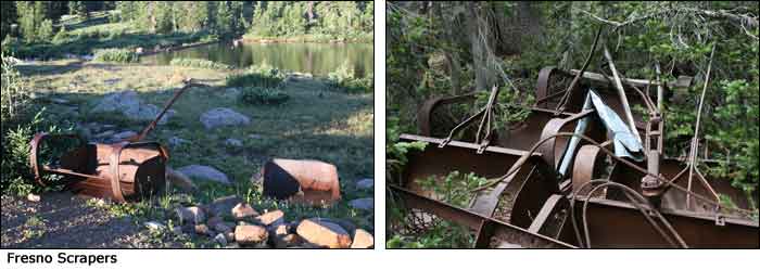
Once at the construction, site special equipment to aid in dam construction was built. Stock-drawn rollers were constructed using corrugated metal filled with concrete. These were used to compact and grade the earthen-fill used for the dams. Other equipment used included plows, graders, tongue scrapers and rooters pulled by horses to excavate, move and grade the rock and soil. Steel team-drawn earth scrapers such as the Fresno Scraper were hauled to the site and functioned to remove and haul earth-fill to dam sites.
 First steps of dam construction consisted of blasting the rocky moraine deposits where the dams were to be located, requiring many caps and sticks of dynamite. Once the rock and soil was loosened, it was then hauled away with horse teams pulling steel scrapers. Borrow pits were excavated, and linear trenches were dug approximately to 10 ft below the natural lake levels for the placement of a water conveyance pipe. Interestingly, the engineering plans indicate a clay foundation was placed at each dam, then covered with tons of earthen-fill, compacted and lined with stone rip-rap facing, which provided height and ballast to form a solid water barrier. However, stabilization efforts excavated a v-notch through the dams and did not actually find examples of these clay core foundations. First steps of dam construction consisted of blasting the rocky moraine deposits where the dams were to be located, requiring many caps and sticks of dynamite. Once the rock and soil was loosened, it was then hauled away with horse teams pulling steel scrapers. Borrow pits were excavated, and linear trenches were dug approximately to 10 ft below the natural lake levels for the placement of a water conveyance pipe. Interestingly, the engineering plans indicate a clay foundation was placed at each dam, then covered with tons of earthen-fill, compacted and lined with stone rip-rap facing, which provided height and ballast to form a solid water barrier. However, stabilization efforts excavated a v-notch through the dams and did not actually find examples of these clay core foundations.
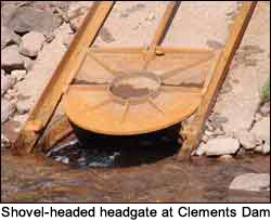 At most dams, some form of gate, such as the steel shovel-headed headgate shown on the left, covered the upstream face of the outlet pipe and a rotating gate wheel raised and lowered the gate to control the amount of water released downstream. This gate was attached to the water intake valve on the water conveyance pipe, which funneled water to the downstream outlet. The downstream outlet was typically a concrete collared outlet. At some dams, such as Deer Lake Dam in Swift Creek Basin (bottom, right photo) and Drift Lake Dam in Garfield Basin, stone collars secured the outlet. At most dams, some form of gate, such as the steel shovel-headed headgate shown on the left, covered the upstream face of the outlet pipe and a rotating gate wheel raised and lowered the gate to control the amount of water released downstream. This gate was attached to the water intake valve on the water conveyance pipe, which funneled water to the downstream outlet. The downstream outlet was typically a concrete collared outlet. At some dams, such as Deer Lake Dam in Swift Creek Basin (bottom, right photo) and Drift Lake Dam in Garfield Basin, stone collars secured the outlet.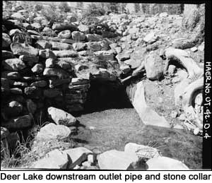
See: Fraser, Clayton B., James A. Jurale, with Robert W. Righter, Beyond the Wasatch: The History of Irrigation in the Uinta Basin and Upper Provo River Area of Utah, edited by Gregory D. Kendrick (1989).
|